Scenario:
A large international ISP has hired you as one of their network engineers. The ISP still has a fairly large customer that is using an older frame-relay network. All of your colleagues are too busy working with MPLS and you are the only one who is capable of fixing frame-relay problems. Whenever router Tilburg is sending major EIGRP updates there are problems with congestion. Think you can tune EIGRP so this network won’t have congestion anymore?
Goal:
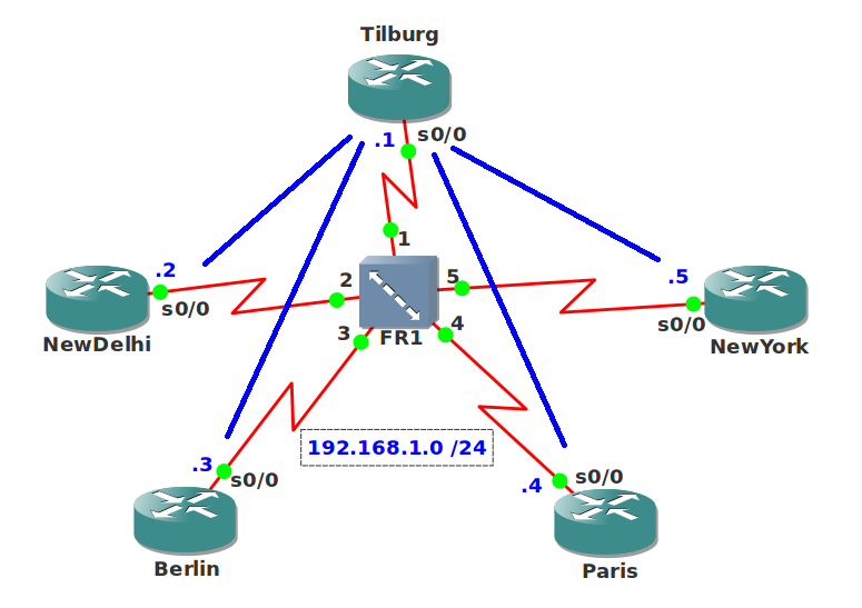
- All IP addresses have been preconfigured for you as specified in the topology picture.
- Every router has a loopback0 interface:
Tilburg: 1.1.1.1 /24
NewDelhi: 2.2.2.2 /24
Berlin: 3.3.3.3 /24
Paris: 4.4.4.4 /24
NewYork: 5.5.5.5 /24 - You are not allowed to make any changes to the frame-relay configurations.
- In this topology you can see 4 spoke routers but in reality there are 10 spoke routers. I didn’t add them all to save CPU power when you run this topology. Each PVC has a CIR of 64kbps.
- Router Tilburg has a serial interface 0/0 that only has a physical bandwidth of 256kbps.
- Configure EIGRP AS 1 on all routers and make sure you have full connectivity.
- Whenever router Tilburg sends EIGRP updates to all spoke routers there is congestion because the physical bandwidth of serial interface s0/0 is only 256kbps.
- Configure your network so the bandwidth reflects the CIR on the PVCs and EIGRP will only use 50% of the CIR.
It took me 1000s of hours reading books and doing labs, making mistakes over and over again until I mastered all the routing protocols for CCNP.
Would you like to be a master of routing too? In a short time without having to read 900 page books or google the answers to your questions and browsing through forums?
I collected all my knowledge and created a single ebook for you that has everything you need to know to become a master of routing.
You will learn all the secrets about EIGRP, frame-relay and more.
Does this sound interesting to you? Take a look here and let me show you how to Master CCNP ROUTE
IOS:
c3640-jk9s-mz.124-16.bin
Topology:
Configuration Files
You need to register to download the GNS3 topology file. (Registration is free!)Once you are logged in you will find the configuration files right here.
The How to Master series helps you to understand complex topics like spanning-tree, VLANs, trunks, OSPF, EIGRP, BGP and more.
Written by René Molenaar - CCIE #41726

i am looking for the sol. of this goal.
please provide the video solution
Hopefully I can record them this week!
Sample config:
Tilburg:
on each subinterface bandwidth 25
On spoke routers:
bandwidth 64
ip bandwidth-percent eigrp 1 19
(25*0.5=12.5 12.5/64=19)
Correct?
Hi Rene,
Any idea when the video solution for this lab will be available ?
Hi Rene…
Can you please post the configuration videos
Thank you
I would set the s0/0 bandwidth on Tilburg to 25kb (256/10=25) and 25kb on every spoke router.
Is this correct?
Taken from Cisco website:
Pure Multipoint Configuration (No Subinterfaces)
In this configuration EIGRP will divide the configured bandwidth evenly across each virtual circuit. You must ensure that this will not overload each virtual circuit. For example, if you have a T1 access line with four 56K VCs, you should configure the bandwidth to be 224Kbps (4 * 56Kbps) in order to avoid dropping packets. If the total bandwidth of the virtual circuits equals or exceeds the access line speed, configure the bandwidth to equal the access line speed. Note that if the virtual circuits are of different capacities, the bandwidth must be set to take into account the lowest capacity virtual circuit.
For instance, if a T1 access line has three 256Kbps VCs and one 56Kbps VC, the bandwidth should be set to 224Kbps (4 * 56Kbps). In such configurations, putting at least the slow virtual circuit onto a point-to-point subinterface is strongly recommended (so that the bandwidth can be raised on the others).
+ add 58% percent bandwidth so each pvc will use around 32kb
[quote=bartsmajdor]I would set the s0/0 bandwidth on Tilburg to 25kb (256/10=25) and 25kb on every spoke router.
Is this correct?
Taken from Cisco website:
Pure Multipoint Configuration (No Subinterfaces)
In this configuration EIGRP will divide the configured bandwidth evenly across each virtual circuit. You must ensure that this will not overload each virtual circuit. For example, if you have a T1 access line with four 56K VCs, you should configure the bandwidth to be 224Kbps (4 * 56Kbps) in order to avoid dropping packets. If the total bandwidth of the virtual circuits equals or exceeds the access line speed, configure the bandwidth to equal the access line speed. Note that if the virtual circuits are of different capacities, the bandwidth must be set to take into account the lowest capacity virtual circuit.
For instance, if a T1 access line has three 256Kbps VCs and one 56Kbps VC, the bandwidth should be set to 224Kbps (4 * 56Kbps). In such configurations, putting at least the slow virtual circuit onto a point-to-point subinterface is strongly recommended (so that the bandwidth can be raised on the others).[/quote]
This is correct. I haven’t had time to record this lab yet, I’ve been very busy…
HI Rene,
like to see solution for this lab,
Hi folks,
In Tilburg:
Set the bandwidth to 256 kbps in serial 0/0.
Totally 4 pvc’s so 256/4= 64 kbps per PVC.
Set the bandwidth percent in Tilburg’s each serial SUB interface to 50%.
50% of 64kbps = 32kbps(50% of CIR Achieved)
Example configuration for only one subinterface(plz do it for all 4 subinterface according to the topology given)
int serial 0/0.1 point-to-point
ip bandwidth-percent eigrp 1 50
In the Spoke:
Set the bandwidth to 64kbps.
Set the bandwidth percent to 50%.
50percent of 64kbps = 32kbps
That’s it.
I Hope am right. Plz correct me if i am wrong. Cheers
If we have 10 PVC 64 kb each
Can we set 64/2*10 to the bandwith of hub router ?
Hi Rene,
please provide the video solution
Was there ever a video solution for this lab created???
The interface bandwidth command will not affect traffic patterns at all. It’s just a reference for IGP protocols. In a real world situation you wouldn’t want to set an interface bandwidth command to change the IGP traffic calculations. To reduce congestion, you have to reduce traffic on the circuit. Therefore, you can remove broadcast, reduce hello packets, frame-relay congestion commands, and change EIGRP traffic percentages. I was able to test this theory by applying a service policy of 8kbs on the interfaces. If you ping the interface continously, you will see the queuing buckets fill up and drop packets. After reducing the congestion, you will notice a change in the traffic pattern. You will actually notice less packets being dropped. You will only notice this after adding the broadcast commands on frame-relay and EIGRP, and then changing the circuit to unicast only traffic + EIGRP traffic percentages.
Below is an example configuration:
policy-map ingress-policy-8kbps
class class-default
police cir 8000
exceed-action drop
int se0/0
ip address 192.168.1.5 255.255.255.0
encapsulation frame-relay
frame-relay map ip 192.168.1.1 501
service-policy input ingress-policy-8kbps
router eigrp 1
neighbor 192.168.1.1 se0/0
no auto
i am looking for the sol. of this goal.
please provide the video solution
Let me know if my solution is correct.
on the hub router
int s0/0
bandwidth 256
on the spokes
(since there are 10 routers, the BW for each spoke’s serial interface is 256/10 = 25 (approx.). I chose 25 coz it will be the best BW allowed for each spoke router
int s0/0
bandwidth 25
then for point-to-point BW pacing goal
since we are required to use 50% of the CIR, hence 64(.5) is 32kbps..
then use the ip bandwidth-percent on the pt-to-pt interfaces of the hub router and the s0/0s of each spoke router.
for hub router
int s0/0.x point-to-point
ip bandwidth-percent eigrp 1 (percent)
the percentage here is
(what percentage?) of 25k is 32k..by simple math that gives you, 128%
so that is
note 10 pt-to-pt interfaces on hub router
int s0/0.x point-to-point
ip bandwidth-percent eigrp 1 128
then for spoke router
int s0/0
ip bandwidth-percent eigrp 1 128
hth,
alvin
You are setting bandwith on a serial interface of the hub router, but this action is incorrect. If you are entering "sh int serial 0/0.101", you can see that bandwith of this subinterface not changed and equal 1544 kbit (the speed T1). The subinterface does not inherit bandwith the serial interface. EIGRP will be used bandwith the subinterface equal 1544. I think, you need set bandwith on every subinterface of hub router.
Thanks for your reply petrovich. I labbed this one out and you are right and I lacked configuring BW on the sub-if.
So the configuration will be
on hub router:
int s0/0
bandwidth 256
int s0/0.1 point-to-point
bandwidth 25
ip bandwidth-percent eigrp 1 128
:
:
int s0/0.10 point-to-point
bandwidth 25
ip bandwidth-percent eigrp 1 128
while on each spoke routers:
int s0/0.1 point-to-point
bandwidth 25
ip bandwidth-percent eigrp 1 128
~ alvin
hey alvin,
why not
int s0/0.1 point-to-point
bandwidth 32
ip bandwidth-percent eigrp 1 100
on spoke router??
My Solution :
As per point to point interfaces you need to divide the bandwidth configured on the interface of the hub on how many PVC you have.
if you will go by 4 PVC, you will have :
256/4 = 64 kbps
Set 64 kbps to the interface and subint of the hub.
so far all interface has the same 64kpbs speed, with this
eigrp will not overwhelm each pvc.
now if you will go by 10PVC, you will have :
256/10 = 25kbps
set 25kbps to the interface and subint of the hub.
but 50% of 25kbps is not equal to 50%of 64kbps pvc speed, which is one of the requirement of the problem.
no worry, as eigrp bandwidth percentage can exceed 100%.
we can set the hub to use at least 128% which is equal to 32kpbs which is 50% of PVC.
problem solved. 🙂
I am confused – the topology shows 192.168.1.0/24 for all routers but in the lab configs Tilburg has the following
interface Serial0/0.102 point-to-point
ip address 192.168.12.1 255.255.255.0
frame-relay interface-dlci 102
!
interface Serial0/0.103 point-to-point
ip address 192.168.13.1 255.255.255.0
frame-relay interface-dlci 103
!
interface Serial0/0.104 point-to-point
ip address 192.168.14.1 255.255.255.0
frame-relay interface-dlci 104
!
interface Serial0/0.105 point-to-point
ip address 192.168.15.1 255.255.255.0
frame-relay interface-dlci 105
Tpeel,
Do not go by the addressing in the topology. Make sure to check all subinterfaces on the Hub router for correct addressing and make sure neighbor relationships are FULL. The Hub should have 4 adjacencies (one to each spoke), while each spoke should have one (to the hub).
I understood about sub-interfaces and the IP addresses set – I was pointing out the diagram showed 192.168.1.0/24 as the address range. I am working on OSPF over Frame-relay 😕 at present and getting my head around that 🙂
Thanks for your help
Tim 😀
I think it is 2 solutions.
1. On hub with bandwidth 25kb/each subinterface. Rest for eigrp 12.5kb
On spoke with bandwidth 64kb, for eigrp rest 32kb.
On hub to bring at 32kb/link we need to raise width 32/12.5= 2.56, and 256%*50%=128%
On spoke we let them untouched.
Verify : eigrp bandwidth percent 128% * 25 kb = 32 kb.
But 32kb * 10 = 320 kb, more than 256kb physical bandwidth of the hub. So this solution is bad.
2. On hub with bandwidth 25kb/each subinterface. Rest for eigrp 12.5kb
On spoke with bandwidth 64kb, for eigrp rest 32kb.
We need to bring down 32kb to 12.5kb. So 12.5/32 = 0.39, and 39%*50%=19%.
On hub we let bandwidth-percent untouched.
Verify: eigrp bandwidth-percent 19 % * 64 = 12.6 exactly like hub. I think this is correct answer.
Yours make sense.
However in my opinion, i see it this way.
10 spokes x 56K bandwidth each.
Hub line 256K bandwidth.
We don’t want each PVC on HUB to become over subscribed (for EIGRP traffic), so:
256 / 10 = 25.6K
HUB:
int ser0/0.1 point-to-point
bandwidth 25
ip bandwidth-percent eigrp 1 50
Keep going for the next 9 point-to-point interfaces on HUB as like shown above.
SPOKE:
int ser0/0.1 point-to-point
bandwidth 25
ip bandwidth-percent eigrp 1 50
So in this scenerio, (25×50) / 100 = 12.5, eigrp won’t use more than 12.5K of bandwidth.
Source:
http://www.cisco.com/c/en/us/support/docs/ip/enhanced-interior-gateway-routing-protocol-eigrp/13672-12.html#hybrid
Correction, each spoke has 64K instead of 56K per my previous note. Just replace 56K with 64K, and it should be OK. sorry for the confusion.
In my opinion it’s simple. 256/10 = 25.6*(0.5) = 12.8Kbps. So you have to insert the bandwidth command on hub interface s0/0 “bandwidth 13”.
I did 12.8/64 = 0.2 or 20%. So the spokes routers should be configured with “ip bandwidth-percent eigrp X 20″and the “bandwidth 64”.