Scenario
After slugging through CCIE Practice lab 1, you’ve returned to the site to find yet another challenge!
Goal:
Nothing has been preconfigured for you! Coordinating instructions are below. All IP addresses begin with 192.168 unless otherwise shown or described.
No static routing, policy-based routing, or default routing is allowed unless explicity stated.
At any point in the lab, you can tune any timers you want (STP, protocols, etc).
Each router should be configured with two loopbacks. “x” is the router number.
Loopback0 = x.x.x.x /32
Loopback1 = xx.xx.xx.xx /32
For example, R1 would have 1.1.1.1/32 and 11.11.11.11/32, R2 would have 2.2.2.2/32 and 22.22.22.22/32, etc.
R2, R3, and R5 all have 16-port switch modules installed. Switch cabling:
R2 F1/12 : R5 F1/12
R2 F1/13 : R5 F1/13
R2 F1/14 : R5 F1/14
R2 F1/15 : R5 F1/15
R3 F1/10 : R5 F1/10
R3 F1/11 : R5 F1/11
Frame Relay DLCI mapping
R1:R2 :: 102:201
R2:R3 :: 203:302
Phase 1: Basic configuration
1. Build the topology as shown in the diagram by making physical connections.
2. Configure all IP addresses and the FR switch as described above and shown in the diagram. Don’t forget the VLAN SVIs!
3. Correct any speed and duplex errors by using the fastest possible line speed and best duplex setting available.
4. R4 should receive it’s IP address via DHCP from R2. The DNS server is 10.0.0.2 and the lease is good for 10 minutes. R2’s F0/0 address is excluded from the pool.
5. The link between R2 and R4 is PPPoE with R2 as the PPPoE server.
Phase 2: Frame Relay and serial connectivity
1. On R1 and R2, configure frame relay. Use a non-proprietary encapsulation form, do not rely on IARP, and use a non-Cisco type of LMI and encapsulation. Pay attention to the IP subnets; they will tell you whether to use P2P or MP links. Ensure you can communicate from R1 to R3. You may use the “broadcast” keyword.
2. R2 and R3 are connected by a direct serial connection and a FR link. Find a way to bundle these two links together; you cannot use FR encapsulation on the directly connected link. Once the links are bundled and verified, secure this connection using a layer 2 feature (IPsec is layer 3).
3. The link between R4 and R5 should be PPP and should use CHAP for authentication. R5, however, should have an alternate of NOT_R5 to confuse attackers.
4. The link between R5 and R6 should be PPP and should use PAP for authentication.
5. The link between R3 and R6 should be PPP and should use PAP for authentication.
Phase 3: LAN Switching
1. R5 is the VTP server using the name VTP123. It should advertise VLANs 235 and 356, both of which should be added to the VLAN database. R3 should accept these VLANs but R3 is not allowed to modify the VLAN database. R2 should ignore this VTP update and should be manually programmed with only VLAN 235 in it’s VLAN database. Do not use a VTP password to accomplish this.
2. Configure R2 as the root for VLAN 235 and R5 as the root for VLAN 1 and VLAN 356. Do not use the “spanning-tree vlan x root primary” command.
3. Bundle F1/12-13 into PortChannel1 and F1/14-15 into PortChannel2 on R2 and R5. Enable static Etherchannel. Both Etherchannels are 802.1Q trunks.
4. VLAN 356 is not allowed towards R2 on any trunk link.
5. To make best use of available links, you decide to load balance VLAN traffic across your trunks. Configure R5 so that VLAN 235 prefers Po2 towards R2. Configure R5 F1/10 interface so that traffic for all VLANs is preferred over F1/11. F1/10 should be the backup link. Do not use backup interfaces or “switchport allowed vlan”.
6. Enable a feature on R3 that will allow it to immediately switch to F1/10 if F1/11 fails. Warning: Sometimes this feature causes weird GNS3 bugs. If you know the feature, you get credit! If it breaks GNS3, then just remove it. The solution is in the description on R3 F1/10 interface.
Phase 4: OSPF
1. Configure OSPF area 0 on R1 loopback2 interface. Make sure LSAs are not sent to this loopback.
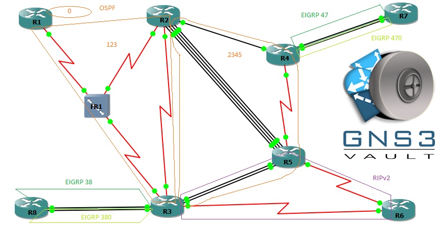
2. Configure OSPF area 123 on all FR interfaces on R1 and R2, as well as the special interface you built on R3. Bring R2 Loopback0 into OSPF this way as well. Do not use the “ip ospf network” command on R1 or R2 FR interfaces. On the special interface between R2 and R3, ensure there is a DR election but the hello packets should not be multicast.
3. Issue the command “area 0 authentication message-digest” on R1.
4. Ensure R1 and R3 can never be DR’s within the two segments you just configured.
5. Configure OSPF area 2345 on the following interfaces:
R2 Vlan235
R2 S0/1
R4 S0/0
R4 S0/1
R5 Vlan235
R5 S0/0
R3 Vlan235
R3 Loopback0 (no LSAs sent here)
R4 Loopback0 (no LSAs sent here)
R5 Loopback0 (no LSAs sent here)
6. R5 should be the DR on the VLAN 235 segment.
7. You are not allowed to use the “ip ospf cost” command anywhere in this lab. Also, you can not modify any interface MTUs at any point, for any reason. Ensure you have full OSPF connectivity.
Phase 6: RIP
1. Configure RIP on R3 Vlan356 and R5 Vlan356.
2. Configure RIP on R3 S0/2, R5 S0/1, and both of R6’s serial interfaces.
3. Advertise R6’s loopback into RIP, and do not send RIP updates to this loopback.
Phase 7: Redistribution
1. Mutually redistribute between OSPF and RIP on R2 and R5. Do not use route tagging. Ensure there are no routing loops and that you have full connectivity.
Phase 8: BGP
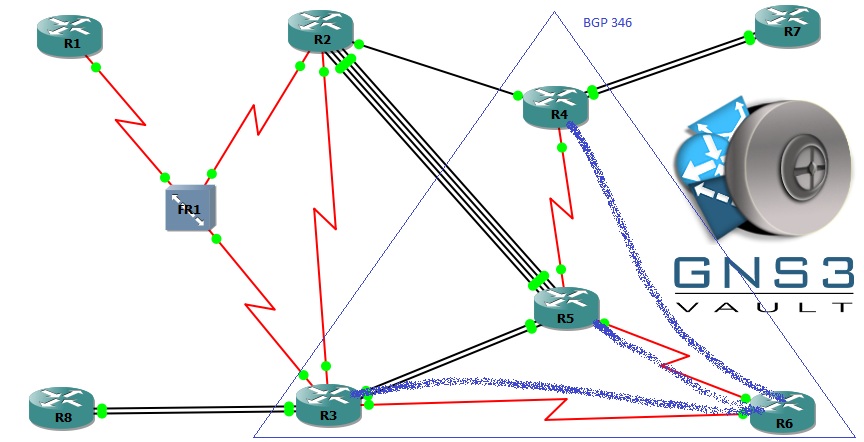
1. Configure BGP 346 on R3, R4, R5, and R6. iBGP peerings are R6-R3, R6-R5, and R6-R4.
2. Advertise the loopback1 addresses on each of these (4) routers into BGP and ensure you have full connectivity between these loopbacks.
Phase 9: MPLS
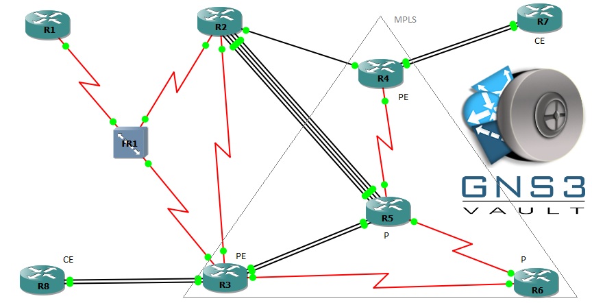
1. Configure R3 in such a way that it forms a neighborship with R8 on both F0/0 and F0/1 (using both EIGRP ASNs). These neighborships should be in different routing tables and should have no knowledge of one another.
2. Configure R4 in such a way that it forms a neighborship with R7 on both F0/0 and F0/1 (using both EIGRP ASNs). These neighborships should be in different routing tables and should have no knowledge of one another.
3. Do not use the “route-target both” command in your configuration, and you cannot manually configure the same import/export RTs within the same VRF, either. For reference, the F0/0 connections on R7 and R8 represent one customer, and the F0/1 connections represent another.
4. You are not allowed to configure any virtual routing tables on R6 or R5; they are not virtual routing aware.
5. Enable end-to-end connectivity from R8 loopback38 to R7 loopback47 (once you configure EIGRP below).
6. Enable end-to-end connectivity from R8 loopback380 to R7 loopback470 (once you configure EIGRP below).
(This is the hardest part of the lab by far!)
Phase 10: EIGRP
1. Configure EIGRP 38 on R8 loopback38 and R8 F0/0. Ensure no EIGRP updates are sent to the loopback.
2. Configure EIGRP 380 on R8 loopback380 and R8 F0/1. Ensure no EIGRP updates are sent to the loopback.
3. Configure EIGRP 47 on R7 loopback47 and R7 F0/0. Ensure no EIGRP updates are sent to the loopback.
4. Configure EIGRP 470 on R7 loopback470 and R7 F0/1. Ensure no EIGRP updates are sent to the loopback.
5. On the R3-R8 F0/0 link, enable an EIGRP feature on R3 that will help save memory by reducing unnecessary EIGRP messages sent by R8 towards R3. This feature should not apply to the R3-R8 F0/1 link.
6. On th R4-R7 F0/1 link, enable EIGRP authentication using a rotating key. The first key is valid from the time you started this lab until one hour from now. The second key is good 30 seconds before the first key expires and is good forever.
7. Enable NTP on R7 and R4 to keep the clocks in sync. R4 is the master. Authenticate all NTP traffic and log all NTP events to the console.
Phase 11: QoS
1. Add a static route on R2 that changes the destination for 3.3.3.3/32 towards the special interface connecting R2 and R3. This route should be installed in the routing table only if the line-protocol on loopback0 is up.
2. Define a QoS policy on R2 that does the following actions for all traffic sent out of the special interface connecting R2 and R3:
* All ICMP traffic should be policed to a CIR of 16 kbps with a sustained burst rate of the CIR, and an excess burst rate of half the CIR. Conforming traffic ic transmitting, traffic that exceeds “bc” should have it’s DSCP set to 0, and traffic that exceeds “be” should be dropped.
* All TELNET traffic should be given 15 percent of the link’s bandwidth. TELNET traffic marked with DSCP EF, if the queue begins to fill, should be randomly dropped to avoid tail drop. After 20 packets are in the queue, 1 in 15 should be dropped, and after 40 packets are in the queue, all should be dropped.
* All HTTP traffic should be given a strict priority 25 percent of the link’s bandwidth. It should be unconditionally set to DSCP 41 and should have TCP header compression enabled.
Phase 12: Multicast
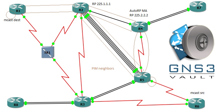
1. Enable PIM-SM on the following interfaces. You cannot enable PIM on any other non-loopback interfaces from this point forward.
R1 S0/0
R2 S0/0.201
R2 “PPPoE interface”
R2 Vlan235
R4 “PPPoE interface”
R4 S0/0
R5 S0/0
R5 S0/1
2. Enable a PIM feature on R2 and R5 so that R3 can never become a PIM neighbor with R2 or R5 on VLAN 235. Any other router, if added to the segment and runs PIM, should be able to form a neighborship.
3. Configure R1 Loopback 2 to join groups 225.1.1.1 (group 1) and 225.2.2.2 (group 2). Group 1 should use a special security feature that only allows it to accept multicast packets from 192.168.56.6. Group 2 will accept packets from any source.
4. R2 is the RP for group 1 and R4 is the RP for group 2. Use AutoRP to make this dynamically learned. R4 is also the mapping agent.
5. Do not use the command “ip pim autorp listener” anywhere in your solution. You are not allowed to use any dense-mode style behavior anywhere in the lab. This means that you must select a router to be the RP for some multicast groups …
6. You are allowed to use exactly (2) static routes in your solution. If you can do it without static routes then you are smarter than I am!
7. Ensure R6 can ping group 1 and group 2 and receive responses. Ensure R5 can ping group 2 only.
Phase 13: IPv6
1. Make up your own IPv6 addresses on all interfaces requiring IPv6 treatment. This includes R1, R3, R4, and R5 loopback0 interfaces.
2. Configure OSPFv3 area 0 between R1 and R2. Use existing DLCI numbers; you are not allowed to add new DLCIs on the FR switch. Ensure their is a DR election on the link but hello packets should be unicast; R1 should never be the DR. You cannot use the “broadcast” keyword. Advertise loopback 0 as well.
3. Configure OSPFv3 area 23 on the special link between R2 and R3. Ensure there is no DR election on the link.
4. Configure OSPFv3 area 38 on both links between R3 and R8. R3 should not allow Type-5 or Type-7 LSAs in area 38, but it should allow Type-3 LSAs.
5. Ensure the F0/0 link between R3-R8 has OSPFv3 authentication enabled.
6. Enable unequal path load balancing on the links between R3 and R8. R8 should send all traffic over F0/0 and R3 should send all traffic for R8 over F0/1. There should be no equal cost load balancing.
7. Configure RIPng using the name RIP6 in accordance with the diagram. Advertise R4 and R5 loopbacks.
8. Mutually redistribute between RIPng and OSPFv3 at R2 and R3. Do not modify administrative distance. Ensure full reachability between networks.
9. R1 should originate a “half-default” route. This route should cover the upper half of all IPv6 addresses (8000:: to FFFF:FFFF….).
10. Ensure you have full connectivity between IPv6 loopbacks.
IOS:
c3725-adventerprisek9-mz.124-7.image
Topology:
Main topology

IGP topology
EGP toplogy
MPLS topology
Multicast topology
IPv6 IGP topology
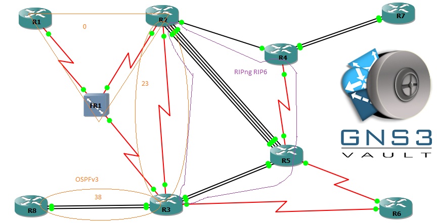
Once you are logged in you will find the configuration files right here.
The How to Master series helps you to understand complex topics like spanning-tree, VLANs, trunks, OSPF, EIGRP, BGP and more.
Written by René Molenaar - CCIE #41726


Pls..share some videos and final configs to this journey 🙂
Some final configs would be nice to look at. Thanks! 🙂
Are they not available?
Been looking for them but am unable to find them for this lab and the CCIE Lab1 as well.
Thank you very much. This has helped me solidify the concepts.
If you can and when free, a third lab with more v5 topics like EIGRP named mode, HMAC etc would be well appreciated.
I am not sure GNS3 can support those features, maybe the newest versions. But thanks for the comment. We can look into that.
Pls..share some videos ,something i can’t understand
Hi Rene, my many thanks for sharing those configs. I have been following your lesson-practices for some while now. I hope I can approach you when and if I may need some assistance. Great job.
Can the .net file be provided please?