Scenario:
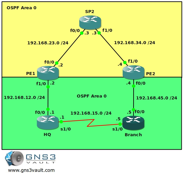
You have been dreaming of starting your own ISP for years and now the moment is finally here. You bought a couple of brand new routers and you are about to implement your MPLS backbone. Your first customer has just signed a contract for connecting two sites so there is nothing stopping you. One of your routers will be the “P” router for the backbone. The other two routers will be used as “PE” router to connect the customer’s end devices. Your customer is running RIP as their (IGP) internal routing protocol. Your backbone will use OSPF as the IGP….time to create your business!
Goal:
- All IP addresses have been preconfigured for you.
- Every router has a loopback0 interfaced configured as following:
HQ: 1.1.1.1 /25
PE1: 2.2.2.2 /25
P2: 3.3.3.3 /25
PE2: 4.4.4.4 /25
BRANCH: 5.5.5.5 /25 - Configure OSPF Area 0 at the provider side (Router PE1, PE2 and P).
- Advertise the loopback interfaces as well in OSPF.
- Ensure you have full reachability in the OSPF domain.
- Configure MPLS on all physical interfaces in the service provider domain, do not configure MPLS on physical interfaces pointing towards the customer.
- Configure VRF “customer” on PE1 and PE2 as following:
RD 100:1
Route-target both 1:100 - On router PE1 and PE2 add the interfaces pointing towards the customer to the VRF you just created.
- Ensure you can ping from within the VRF, try this as following on PE1:
ping vrf customer 192.168.12.1 - Configure OSPF Area 0 on router HQ and Branch. Advertise the loopbacks as well.
- Configure OSPF on router PE1 and PE2 for the correct VRF “customer”.
- Ensure you receive prefixes from the customer routers on your PE routers.
- Configure BGP AS 1 between Router PE1 and PE2.
- Configure the correct BGP address families and make sure communities are sent between neighbors.
- Redistribute OSPF into BGP, use the correct address-family for the VRF “customer”.
- Ensure you have full connectivity between router HQ and Branch. You should see each other’s OSPF routes that have been carried over the service provider’s MPLS backbone.
- The OSPF prefixes on the HQ and Branch router are showing up as O IA (Inter-Area). Change this so they show up as E2 routes.
- Enable OSPF on the serial link between router HQ and Branch, this will be a backup link in case the MPLS Backbone crashes.
- You notice packets are beint sent through the backup serial link stead of the MPLS Backbone. Make sure all packets are sent through the MPLS Backbone without removing OSPF on the serial link or shutting down the interface.
IOS:
c3640-jk9s-mz.124-16.bin
Topology:
Video Solution:
Configuration Files
You need to register to download the GNS3 topology file. (Registration is free!)Once you are logged in you will find the configuration files right here.
The How to Master series helps you to understand complex topics like spanning-tree, VLANs, trunks, OSPF, EIGRP, BGP and more.
Written by René Molenaar - CCIE #41726

“The OSPF prefixes on the HQ and Branch router are showing up as O IA (Inter-Area). Change this so they show up as E2 routes.”
Having some issue with that one… does it have ANYTHING to do with changing the domain-id? If so, do I change it on the CEs or PEs?
I am proud to say however I got everything else working, freaking epic lab. I start work with an ISP tomorrow, and I want to make sure I have at least a little MPLS VPN before going through training. Makes me wish Cisco would’ve kept a little MPLS on the CCNP track.
Hi Jon,
If you got the MPLS part running you are 99% done. Google for “OSPF Sham Link” and you’ll find the answer.
Good luck at the ISP! 🙂
Hi Guys
I am getting following message when I configure ospf instance on vrf to make adjencies to HQ and Branch
%VRF specified does not match this router
Any idea why this is happening.
You get this error even though you created the VRF before?
thanks
great stuff…Got it running 100% after second attempt. I got it up 95 % the first time but i wanted everything to be perfect. The video also helped…
Hi guys,
Why in the customer edge the branch router is configured with ospf process id 1 and on the HQ router it is configured on OSPF process id 2.
Thanks and Regards,
Charlot Attard
The OSPF process-ID is locally significant to each router so it doesn’t have to be the same on both routers and they will still exchange OSPF routes. If this were EIGRP then the AS for EIGRP would have to match in order for routes to be exchanged.
i cant ipsec on MPLS VPN
on networkslessons.com ON THE EXAMPLE ONFIGURATION MPLS VPN MP-BGP (Multi-Protocol Border Gateway Protocol) ET DEUX Virtual Routing and Forwarding VRFs
——-OSPF VRF
router ospf 10 vrf BLUE
redistribute bgp 10 subnets
network 11.11.11.0 0.0.0.255 area 0
——-BGP R1
router bgp 10
bgp router-id 1.1.1.1
neighbor 3.3.3.3 remote-as 10
neighbor 3.3.3.3 update-source Loopback0
neighbor 3.3.3.3 next-hop-self
address-family vpnv4
neighbor 3.3.3.3 activate
neighbor 3.3.3.3 send-community both
exit
address-family ipv4 vrf BLUE
redistribute ospf 10 vrf BLUE
Really nice lab. You can also accomplish the same result without using sham-links. just use area 1 for the serial links between HQ and Branch router 🙂