Scenario:
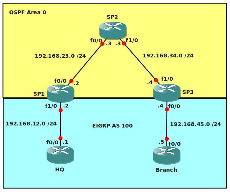
Service provider “StoryTellers” is intrigued by your performance so far, before they allow you to even look at their production MPLS backbone there is another lab they would like you to configure another lab. By using MPLS VPN’s it’s possible to send customer routes over the provider network. OSPF will be configured in the service provider domain (Router SP1, SP2 and SP3), the customer will be using EIGRP.
Goal:
- Configure all IP addresses as specified in the topology picture.
- Configure a loopback0 interface on each router:
HQ: 1.1.1.1 /25
SP1: 2.2.2.2 /25
SP2: 3.3.3.3 /25
SP3: 4.4.4.4 /25
BRANCH: 5.5.5.5 /25 - Configure OSPF Area 0 at the provider side (Router SP1, SP2 and SP3).
- Advertise the loopback interfaces as well in OSPF.
- Ensure you have full reachability in the OSPF domain.
- Configure MPLS on all physical interfaces in the service provider domain, do not configure MPLS on physical interfaces pointing towards the customer.
- Force MPLS to use the loopback interface as router-id.
- Configure VRF “customer” on SP1 and SP3 as following:
RD 100:1
Route-target both 1:100 - On router SP1 and SP3 add the interfaces pointing towards the customer to the VRF you just created.
- Ensure you can ping from within the VRF, try this as following on SP1:
ping vrf customer 192.168.12.1 - Configure EIGRP AS 100 on router HQ and Branch. Advertise the loopbacks as well.
- Disable EIGRP auto-summary.
- Configure EIGRP on router SP1 and SP3 for the correct VRF “customer”.
- Ensure you have established a EIGRP neighbor relationship between Router HQ and SP1, and between SP3 and Branch.
- See if you have learned routes by using “show ip route vrf customer”.
- Configure BGP AS 1 between Router SP1 and SP3, make sure updates are sources from the loopback interface.
- Configure the correct BGP address families and make sure communities are sent between neighbors.
- Redistribute EIGRP into BGP, use the correct address-family for the VRF “customer”.
- Redistribute the information from BGP back into EIGRP, use the following metrics:
bandwidth: 64kbps
delay: 1000
reliability: 255
load: 1
MTU: 1500 - Ensure you have full connectivity between router HQ and Branch. You should see each other’s EIGRP routes that have been carried over the service provider’s MPLS backbone.
- Optional: Replace the Customer’s EIGRP with OSPF / RIP or BGP and achieve the same result.
IOS:
c3640-jk9s-mz.124-16.bin
Topology:
Video Solution:
Configuration Files
You need to register to download the GNS3 topology file. (Registration is free!)Once you are logged in you will find the configuration files right here.
Do you want your CCNA or CCNP Certificate?
The How to Master series helps you to understand complex topics like spanning-tree, VLANs, trunks, OSPF, EIGRP, BGP and more.
Written by René Molenaar - CCIE #41726

Do I understand correctly that 3.3.3.3/30 is the broadcast address for subnet 3.3.3.0/30?
Also, is 4.4.4.4/30 the subnet address for 4.4.4.4/30?
If so, how can these be assigned to interfaces? I keep getting “bad mask” errors when I try.
For now, I will just use /29, and see how that goes…
I am a member and I have done the registration and yet I do not see any download link? Can someone advise?
Hi
Only i can download the topology.But i need the configuration of the each router.Can anyone share the configuration for the above topology as i am in need.
Thanks in advance
Mr.KD
About the loopbacks, I messed up on that one…you are correct Doug. 3.3.3.3/30 is a broadcast address. I changed the loopbacks all to /25’s, it doesn’t matter much what kind of address you have on the loopbacks.
Frank, the download link is at the bottom of every article…below the topology picture.
Mr.Kd, what kind of config would you like to see here? a basic config which has the IP addresses or a final configuration with the working solution? Right now I don’t supply any configs but I think I will in the future…it’s very time consuming to create ‘startup’ configs and ‘final’ configs as well.
Hi Rene
I am new to MPLS and so i just want to know how to configure MPLS for the above topology.So i request for the configuration so that i will get some ideas and i can create my own topologies.
Thanks For Your Reply
KD
Dear All
Please Can anyone the configuration for the above topology.Please upload r paste the configuration as comment.
Thanks in Advance
Kd
I did this one of top of my head, but it should be pretty accurate. I didn’t include the OSPF part for the backbone, just the MPLS.
// SP1, SP2 and SP3 should have MPLS enabled on the interfaces towards each other…NOT to the customer!
router (config)# interface f0/0
router (config)# mpls ip
// force MPLS to use the loopback’s router ID:
router (config) mpls ldp router-id loopback0
// now the VRF part. A VRF is like a ‘virtual routing table’, kinda like a VLAN but now for L3. Let’s create the VRF first, you need to do this on SP1 and SP3:
router (config)# ip vrf CUSTOMER
Router(config-vrf)#
// now we setup the RD (route distinguisher) which is needed to make the customers prefixes unique in our MPLS VPN setup.
Router(config-vrf)# rd 100:1
// Next step is to configure the correct route-target. The RT is what ‘creates’ the VPN:
Router(config-vrf)# route-target import 1:100
Router(config-vrf)# route-target export 1:100
// Now we need to add the interfaces pointing towards the customer into the correct VRF, do this on SP1 and SP3 (example is for SP1):
Router(config)# interface f1/0
Router(config-if)# ip vrf forwarding CUSTOMER
// you need to reassign the IP address…but it will tell you.
Try to ping the customer router from the VRF: (example SP1)
// ping vrf CUSTOMER 192.168.45.5
// Now you need to enable routing between the PE routers and the customer router, and we are using EIGRP. The difference is you need to specify the VRF when configuring EIGRP, this is how you do it:
Router(config)# Router EIGRP 100
Router(config-router)#address-family ipv4 vrf CUSTOMER
// then add all the network statements there…
// At this moment, you should have a working EIGRP between the SP and the Customer.
// You should have MPLS running on the SP routers.
// The next step is to get BGP going between SP1 and SP3, we’ll use multi-protocol BGP (MP-BGP) to get those prefixes to the other side. You don’t need to configure BGP on SP2!
// example is for SP1
Router(config)#router bgp 1
Router(config-router)# neighbor 4.4.4.4 remote-as 1
Router(config-router)# neighbor 4.4.4.4 update-source loopback0
// we need to send community information:
Router(config-router)# address-family vpnv4
Router(config-router-af)# neighbor 4.4.4.4 activate
Router(config-router-af)# neighbor 4.4.4.4 send-community extended
// Now we want to get those prefixes to the other side, we need to redistribute from EIGRP to BGP and the other way around.
Router(config)#router bgp 1
Router(config-router)#address-family ipv4 unicast
Router(config-router-af)#redistribute eigrp 100
// and from BGP to EIGRP, remember that you NEED to supply the metrics for EIGRP!
Router(config)# Router EIGRP 100
Router(config-router)#address-family ipv4 vrf CUSTOMER
Router(config-router-af)#redistribute bgp 1 metric 64000 100 255 1 1500
That should be it, these commands should be enough to help you to complete the lab.
Just keep in mind, MPLS itself is just a single command (mpls ip) but there is a lot of knowledge you need beforehand:
– IP Routing
– BGP
– OSPF / EIGRP
– VRF’s
This might make it more difficult.
I’ll create a video how to solve this lab real soon, this one seems to be popular…:)
Good luck!
I just added the video solution + final configs.
Now see if you can do the advanced MPLS VPN lab after this 😉
can you give me the video please
Dear Rene
Thanks a lot for the Video Tutorials and now i got some idea how to configure the MPLS and awaiting for more topologies to come 🙂
Thanks a lot
KD
Glad you like it 😉 With the same topology you can try to have RIP, OSPF or BGP exchanged for the customer…it’s kinda the same but a little bit different.
Good luck
Dear Rene
I configured the same and working fine.But i have some doubts to clarify.
Can you please explain,what is the use of RD and Route-Target and please explain using which criteria we assigned RD 100:1 and Route-Target 1:100.
Please excuse if it is a silly question.
Thanks in Advance
KD
No problem.
The RD (Route Distinguisher) is to make a prefix “unique”.
Let’s say you have Customer A and Customer B…and they both use the 10.0.0.0/8 prefix then you have a problem.
By adding a RD to the prefix you create a “unique” value.
You can pick whatever number you like for the RD, i just made something up.
The Route-Target is used to determine what prefixes you want to import or export, this is what makes the VPN.
Let’s say you have Customer A and Customer B, they each have 2 sites.
You can use RT 100:1 for Customer A so the 2 sites can talk to each other.
Use RT 200:2 for Customer B so the 2 sites can talk to each other.
Now let’s say Customer A and B want to connect to each other, they each have a HQ site and the 2 HQ’s need to be able to communicate with each other.
You can create another RT, for example 102:12 and use it to let the HQ’s communicate with each other.
If you try the Advanced MPLS lab it will make more sense 🙂
Dear Rene
Thanks a lot for ur xplanation.
I just want to know
using the above topology but with some modification like below
SP1 >> Ethernet Switch >> HQ_A n Branch_B
SP3 >> Ethernet Switch >> HQ_B n Branch_A
If i make a scenario like this can i create 2 VLANS, 1 for HQ_A n Branch_A and the next VLAN for HQ_B n Branch_B in the SP1 n SP3.
And For HQ_A n Branch_A routing protocol EIGRP
and for HQ_B n Branch_B routing protocol RIP
Will it works like this.Please suggest ur ideas.
I think there is no modification in the P ie SP2.
Please suggest and gimme some ideas to work it out.
If everything goes fine shall i share the lab with the configuration over here.
Thanks & Regards
KD
Hi KD,
So if I understand correctly…you want to do this
SP1 SWITCH vlan 10+20
Connect HQ-A in Vlan10
Connect Branch-B in vlan 20
SP3 SWITCH vlan 10+20
Connect HQ-B in vlan 20
Connect Branch-A in vlan 10
If you would build a trunk from the switch to the router and create sub-interfaces on the SP routers…that would work, but why would you want to do this? This isn’t something you would see or do in a real life situation..
Keep in mind a switch is a layer2 vlan, and a VRF is kinda like a “layer 3 vlan”
Rene
[quote]Ensure you can ping from within the VRF, try this as following on SP1:
ping vrf customer 192.168.45.4[/quote]
This won’t work since we don’t have BGP yet. We should ping either from SP3 or .12.1
BTW, thanks! You’re doing a good job.
thanks! you are right, just fixed the IP address in the article 😉
/o all,
From the start of the posts I noted a one side of a coin and then the other. I see that some issues were addressed with the “config” and then a video added. Hats off to Rene; I’ve been looking at topologies in manuals, books, PDFs and building from them and having to look up a log of stuff along the way. I have found many errors from Authors and I have learned a lot more by having to look things up to make it work. I lost several hours worth of study time from today this evening, but I then went the extra mile to ensure that I save my topologies correctly, as I will work on something and then switch over for a while due to something I read. It can be good to have config’s to compare against but I am really glad that when I download a lab I have to build out from the image.
Rene, if you decide to add completed configs, can you still have it so we have to… well there is always write erase… wr reload ;).
Bogard
(very long day, pardon typos…)
;D
Need sleep… I see there are two different labs … thanks again.
Bogard
Hi Bogard,
Seems you had a long day of labs 😛
About the configs..I’m trying to add a startup-config to make life easier, and a final config to compare your result against.
Of course there’s always the video solution to follow your progress.
Good luck 🙂
Rene
Dear Rene
How r u. Seems to be no labs updated for MPLS for a long time. Is it possible to share our labs….
Hi Mr Kd!
I’m doing fine thanks, I hope you as well 🙂
I’ve been kinda busy with work so I didn’t have time for MPLS labs…if you have some topologies and tasks please send them over, i’ll wrap them into a nice article for the site!
Rene
Speaking for myself… I would welcome more labs. The more the better. In response to Rene’s post regarding the start up config, I have several in as text files that I use for a always needed basics… if your using DHCP Pool & exclusions, router – EIGRP/OSPF/ect {AS#’s} XXXX. Line COn 0 settings… ect.
Thanks again for the site,
[i]JCB[/i]
its so helpul in our studies…. more labs wil b helpful…..
its so nice…
What program is being used to manage the console windows with the tabs
I’m using Ubuntu with the Gnome Terminal Tabs or Konsole. Check my blogpost here with the video:
http://gns3vault.com/161-terminal-tabs-in-linux-ubuntu.html
Ok so I am new to this and would like to know how to get the IOS images to work. I have found a bunch of IOS .bin files and tried loading them into the GSN3 program but when I try to load the topology from the file above it tells me that my IOS files are in bad paremeter. Any ideas and where did you guys get yours??
Thanks
DT- really the only solution if you’re unable to get the same IOS version is to build the lab from scratch. I do the same thing with my labs. Doesn’t take too much longer…. 😛
To configure IBGP between SP1 & SP3 why didnt you use inside the address family ?
The BGP configuration between SP1 and SP3 is a normal default BGP setup:
router bgp 1
no synchronization
bgp log-neighbor-changes
neighbor 4.4.4.4 remote-as 1
neighbor 4.4.4.4 update-source Loopback0
no auto-summary
The only additional requirement is that you enable [b]address family VPN[/b] because you need the RD along with the prefix.
very good practice 🙂
it’s interesting to note when configuring the bgp vpnv4 send-community parameter that can appear an error message regarding the peering between bgp neighbors along the loopback interface. As i experienced the problem during the configuration i received a message like :”G;P-4-VPNV4NH_MASK : Nexthop 4.4.4.4 may not be reachable from neigbor 2.2.2.2 – not /32 mask”. After wonder around some possible causes of the problem i remembered that changing the ospf network type we can influence the appearance of the mask of loopback interface. As we were running ospf i changed that under lo0 and everything worked like charme.So bgp expect always an host mask to form neighborship over vpnv4 address-family and if we pass it a network mask the neighborship will fail anyway.
Hi Lev,
Quick question, on the routers where you saw this error you already had MPLS LDP enabled on the interface? If so…what happens when you disable MPLS and keep the /24 on the interface without changing the OSPF network type?
Rene
Hi Rene,
yes the mpls part was completed, and the behaviour is the same without mpls enabled. I’ve paid more attention this time to the error and i noted that the redistribution of eigrp into bgp trigger the notification. It’s like if eigrp routes before to reach bgp are influenced by ospf net-type. But i honestly can’t figured out why because until have no redistribution seems everything fine…what you think about it?
Hi Lev,
Interesting. I thought it was only MPLS that had trouble with the /32. It’s something i’ll check in a lab…interesting 🙂
I have just logged out and in again, i can see them now.
Many thanks 🙂
Hi Rene,
I m also not able to see the topology file. Is it a zip. file or sth else? i have downloaded topologies for some other labs like VRF-Lite but that one. Could you please have a look?
Even if im already registered i only see this:
[b]You need to register to be able to download the GNS3 Topology File. (Registration is Free!)[/b]
Thanks.
Hello Ersan,
If you login you can see them right below the Video. two zip files…startup and final configurations.
Just in case here’s the download link:
http://gns3vault.com/attachments/article/79/MPLSVPNBasic.zip
Good luck!
Rene
Hi, Firstly I’d like to thank you for this lab, the resources and the videos, they’ve been very helpful. I’ve been working through the lab solution on your videos and I’ve gotten right to the end of Part 3. However the final 2 pings don’t work for me. Even when I download the Final Configs from here, the last 2 pings don’t work for me. Does anyone know why? Or what I could do to check?
I have been following the commands in the videos one by one and everything looks identical to your results e.g. if I run the “show ip route vrf CUSTOMER” command I get the same result as in the video. As I said it’s just the last two pings to ensure that the HQ and the Branch have end to end connectivity that is failing.
Thanks,
John
Apologies, I just loaded up the topology and the configs again, and the ping is working this time. It’s a bit of a mystery to be honest as I haven’t done anything differently from last time. At least it’s working now anyway, so thanks again!
Hi John,
There are a number of things to check when you are troubleshooting MPLS:
1. Check the BGP adjacency between the PE routers.
2. Check the VRF routing table and see if you can ping from the PE by using the VRF table (ping vrf
3. Check the BGP and IGP (OSPF, RIP, EIGRP) table/database to see if your redistribution is ok.
4. You can also check if there’s a label by using the “show mpls ldp bindings” command.
It depends on the ISP solution, it’s possible that you will get an Ethernet connection from the ISP to the customer.
For some of the labs I chose FastEthernet because you won’t have any layer1 or layer2 issues. If the lab is about MPLS I don’t want people to start struggling with layer1 or layer2 frame-relay issues or anything else so they only have to focus on MPLS 🙂
Question: Why use two Routing Protocols Within the Service Provider. Is this a realistic scenario ?? would the service Provider simple use a BGP route between them and the Customer?? Just curious. .
This is a good example of a real MPLS network. This is what happens:
– Within the MPLS “core” we will run an IGP like OSPF to advertise all the loopback interfaces.
– All the PE routers will run IBGP to exchange routing information.
– Beween the PE and CE (customer) routers you can use whatever routing protocol you like…OSPF, EIGRP but also BGP. It depends on the customer requirements.
Keep in mind that whatever the customer advertises to you will be stored in a VRF (virtual routing table).
I notice that mostly all the labs use Fast-Ethernet or Ethernet for making connection would WAN links be a more realistic representation of ISP connections over distance to the Customer or is their a draw back to this approach ??
I use the Ethernet / FastEthernet links to keep things simple. In this lab I’m just focusing on the MPLS part and it would be bad if you also have to think about layer 2 issues with PPP, HDLC or Frame-Relay 🙂
Hi Rene,
I would like to thank you for the free video lab’s. I took a look at all the labs. I wached the basic mpls vpn video and I appreciated so much that I tried to implment it in my own and it took me so much time to be able to do it.
I have only a small feedback, namely when implementing the video’s. My remak is that you type very fast and ypu give very little explanation fo the command you are enering. I am CCNA and have a baisc MPLS and routing protocols and theri implementation.
So, please try to have more time during you explanation especially for the beginners and your video’s will be very valuable and competitive. May thanks for help.
Hi Mobazi,
Thanks for your kind words and comments. In my future videos I’ll make sure to type a bit slower and take my time to explain things. I do "assume" however that people have read/learned a bit about the background theory of the protocols because it’s hard to explain theory + the implementation at the same time 🙂 I hope it’s helpful to you and i’ll do my best in the future!
Rene
excellent LAB loved watching it….. Appreciation and thank you for the effort…. One thing I would like to notify here is I am not able to download the zip files attached to LAB can you please help….
Hi Mohammed,
Once you have registered and logged in you should be able to see the attachments of the bottom of each article. Can you see them?
Rene
Thanks Rene
your welcome!
thank you very much
your welcome!
Hi Gurus,
I want to connect one Server with SP1 and one Server with SP3.Say server ips are (SP1-Server-192.168.2.1/30) and (SP3-Server-192.168.3.1/30). Do i need to add these networks to eigrp AS 100?. Actually i want to access these servers from hosts connected to Branch and HQ.
You will have to advertise these networks in EIGRP. They will be redistributed into BGP and forwarded across the MPLS backbone.
You can test this by adding additional loopback interfaces on HQ and Branch and advertise these into EIGRP.
[b]excellent lab matey..
just had a question though.
when i do a traceroute from either the HQ or the Branch, the MPLS backbone routers come up in the list.
i did do a no mpls ip propogate-ttl forwarded but that didn’t help.
i also did a no mpls ip propagate-ttl and that removed only one hop router from being show.
default traceroute:
HQ#traceroute 5.5.5.5
Type escape sequence to abort.
Tracing the route to 5.5.5.5
1 192.168.12.2 132 msec 80 msec 52 msec
2 192.168.23.3 [MPLS: Labels 17/22 Exp 0] 340 msec 464 msec 408 msec
3 192.168.45.4 [MPLS: Label 22 Exp 0] 288 msec 268 msec 208 msec
4 192.168.45.5 400 msec * 424 msec
after running a no mpls ip propagate-ttl on all my mpls backbone
HQ#traceroute 5.5.5.5
Type escape sequence to abort.
Tracing the route to 5.5.5.5
1 192.168.12.2 184 msec 92 msec 40 msec
2 192.168.45.4 [MPLS: Label 22 Exp 0] 204 msec 348 msec 408 msec
3 192.168.45.5 308 msec * 720 msec
how do i hide that second hop?
cheers for the lab..
[/b]
edit: is this related to PHP that i am seeing this?
You see the last hop because of PHP (Penultimate Hop Popping). I’m not sure if we can disable the last hop in the traceroute showing up.
thanks mate. let me try a php on the sp2 router and see what happens.
lastly I had a question regarding the route target and rd.
should the rd and the rt be unique in the whole mpls backbone domain? if yes, why?
The RD (Route-Distuingisher) is used to make unique VPN routers. If multiple customers would use the 10.0.0.0/8 network or something else then it’s the RD that makes a "unique" VPN route. If you would use the same RD number we could have duplicates so yes it should be a unique value.
The RT (Route-Target) is used to import or export prefixes, it should be unique because otherwise you might import or export prefixes that you didn’t intend to.
I think that sounds about right 🙂
Hey, I had a bit of a hard time making this work and in the end it was because of a tiny difference in my configuration. Can someone help me understand the reason for this?:
– When I first did all the configuration, I didn’t use the "ip ospf network point-to-point" on the PE loopback interfaces. The result was that there was no end-to-end communication between the customer sites.
– I compared with the final configs and since this command was the only thing I was missing I thought I’d give it a try. Immediately after issuing the command on both sides, end-to-end communication started working perfectly!
Can somebody explain to me why this happens? Thanks
I might also add that although there was no end-to-end communication, route propagation was working (HQ routes were being propagated to the branch end) and PE-to-PE communication via the loopbacks was working as well. This made my troubleshooting a bit harder because I didn’t understand where the problem was.
It’s because OSPF by default ALWAYS advertises a loopback interface as /32. If you configure a /24 subnet mask on the loopback interface then there will be a mismatch. OSPF advertises a /32 while you have a label for a /24 network. Changing the network type to something else (not loopback) will make OSPF advertise the network as whatever you configured on the interface. Another option is configuring a /32 subnet mask on the loopback interface.
Hey Rene, I cleared my MPLS exam yesterday and used your labs to practice the concepts. Just want to thank you for providing this resource. Look forward to doing more such labs.
Cheers,
Aditya
Hello Aditya,
Congratulations! I’m glad my labs were useful to you.
Greetings,
Rene
Great Lab!!!!!
Thanks 🙂
Renee,
This is a well put together intro to MPLS, I’m loving it.
I have a question. When configuring the vrf rd and route-target, you used 100:1 and 1:100 respectively. I have two questions:
1. Do these numbers relate to OSPF PID and EIGRP ASN because they must, or because of convenience and simplicity? Put another way, do these numbers need to match the PID and ASN numbers to function.
2. Could you explain the ordering (100:1 for rd and 1:100 for route-target) and is this also important?
Matt
Ok, now I am seeing that you used EIGRP ASN 100 and 1 for the customer and provider processes, respectively. I think get it. It has nothing to do with the OSPF process–that’s just for provider internal connectivity…I’m stupid!
I’m thinking that the vrf rd and route-target commands are telling the router to "translate" or "connect" the customer’s EIGRP PID 100 into the internal provider EIGRP PID 1 and vice versa. Correct?
It’s more of a coincidence that I picked these numbers. The RD (Route Distinguisher) is used to add "something extra" to a prefix so that it’s 100% unique. We do this in case customers have the same prefix. By adding the RD it’s a "unique prefix".
The RT (Route Target) is kinda like a label…it helps us to select what we want to import/export.
Hi Rene,
I’m new to GNS3, and I have some basic questions 🙂
Did you use the same type of routers (c 3600) in this lab with image c3640-jk9s-mz.124-16.bin ? I’m asking this because I read somewhere that to configure MPLS VPN we need at least C7200 for PE routers.
Thanks
Hi Bobi,
I used the C3640 images, they can run MPLS without any issues. Maybe some features like xconnect (pseudowire) can only be done on the 7200 routers.
If you want to see what routers I used, just open the topology.net file in notepad/wordpad and you’ll see the IOS image.
Rene
Hi Rene,
This is a very good lab and I loved doing it. Thanks to preconfigured routers, which was usually much of a pain in each lab.
Also, I can see the routes being exchanged across the MPLS cloud and see them in the routing tables of the customers HQ and branch, however I’m not able to ping them. Even not able to ping the learnt routes from the PEs.
Did some troubleshooting, but in vain., Any clues?
Thanks.
If you post your configs in the forum we can take a look. Are you able to ping the PE routers from the customer routers?
Any ideas why I am getting (tdp) for my default instead of (ldp)? Why am I getting "Tag switching has not been enabled."?
I followed the lab exactly as it is shown on youtube. Hmm
I am on Video 1/3 on youtube (8:21). I am trying to get MPLS enabled properly on SP1, SP2, SP3.
[IMG]http://i.imgur.com/MqIZg.png[/IMG]
There’s LDP and TDP. TDP is the Cisco labeling protocol if I’m correct. It probably depends on the IOS version that you are using which one is the default. You can change it however.
I think if you go the interface level you can change it with the "mpls label protocol" command.
I found that even when I started the lab using a different 3640 IOS than the one mentioned in this article, the MPLS IP command didn’t work so well.
I went back, used the EXACT IOS in your article, and build a brand new GNS3 project, then everything worked perfectly.
Good to hear that it’s working now.
i am waiting for your reply for my below question….
When i tried the above lab, my BGP doesnt peer – even after stripping it – see below
—————————————-
router bgp 1
no synchronization
bgp log-neighbor-changes
neighbor 192.168.34.4 remote-as 1
neighbor 192.168.34.4 ebgp-multihop 30
neighbor 192.168.34.4 update-source Loopback0
no auto-summary
!
Connectivity test —- SP1#traceroute 192.168.34.4 source 2.2.2.2
Type escape sequence to abort.
Tracing the route to 192.168.34.4
1 192.168.23.3 20 msec 60 msec 20 msec
2 192.168.34.4 16 msec 36 msec *
SP1#
————————–
SP3#traceroute 192.168.23.2 source 4.4.4.4
Type escape sequence to abort.
Tracing the route to 192.168.23.2
1 192.168.34.3 24 msec 24 msec 28 msec
2 192.168.23.2 20 msec 36 msec *
SP3#
!
router bgp 1
no synchronization
bgp log-neighbor-changes
neighbor 192.168.23.2 remote-as 1
neighbor 192.168.23.2 ebgp-multihop 30
neighbor 192.168.23.2 update-source Loopback0
no auto-summary
!
____________________________________
Regarding the EIGRP configuration for the VRF, does the difference in AS number for customer and PE router matter ? e.g from the video you configured eigrp AS 1 and on the VRF you configured AS number 100. what if i configured AS100 for PE router and 100 for customer AS on the address family
have figured the problem out and finalized the lab. thanks.
It is great information for CCNP shooting lab, I am new & thanks for information …
Hi everyone , please How configure frame- relay between PE and CE ?
VPN Level 2
I have some queries going through video solution. Please take your effort to clear my doubts.
what is difference b/w Route Target Both command and route target export and Import both commands in the router. Because u used Route target both on SP1 and route target export as well as import in SP3, can we use route target both on same router and what effect will gave only export or import on SP routers
2nd Question.
BGP
u create address-family vpvn4 under BGP, what effect will it take address-family vpvn4 unicast of SP routers?
3rd question
on SP1 u created neighbour 4.4.4.4 send-community both
but
SP3 u created neigbour 2.2.2.2 send-community extended..
what is difference of this two.. why cant we use send-community both on SP3 is well..
Please explain these 3 question.. on each function(export,import,extended and both as well unicast) key command i asked queries..
hi , how can i see video solution for this scenario ??
Hi,
I cannot find autonomous-system command. i am using
(C7200-ADVENTERPRISEK9_SNA-M), Version 15.0(1)M3, RELEASE SOFTWARE (fc2)
I also did the Lab using 7200 IOS image and U will not find the ‘autonomous-system ‘ command form the list…just type the whole command manually and enter. the command will be accepted.
thank you, your lab is excellent
mpls ip is not a valid command on my routers?
Cisco IOS Software, 3600 Software (C3640-IK9S-M), Version 12.4(16), RELEASE SOFTWARE (fc1)
Do I not have the correct IOS?
Hi Rene,
Thanks for a great lab.
Can I ask why the SP needs to run BGP and peer the 2 PE routers with iBGP in order for the customer connectivity?
Could it just work by redistributing EIGRP into OSPF already running?
thanks!
Mark.
Thank you
need more of MPLS labs, and if you can add QOS LABS, would be great
Hi Rene
Thanks for all the lessons, I think you might have used a wrong gns3 topology for this lab.please double check this. The lab topology that is shown here and the one that is downloadable for gns 3 are different and hence one cannot do the lab. Thanks!
Excellent Lab.. my first adventure with MPLS, BGP, EIGRP
Now I understand a lot more than before
Awesome tutorial…..Had a good understanding of MPLS and was looking for some conf examples.
Your toplogy and explanation was ver helpful. Keep up the good work. Looking forward to the other advanced MPLS stuff on your website 🙂
Dear Rene,
i becoming a big fan of you. You are doing really impressive job. God bless you brother and keep the nice job.
Besides, are there any other uploads coming like Advanced MPLS
can you tell me the main advantages of this network
Great labs.. also great explanation… keep up the good work!!
However.. whta perhaps will be handy.. is to post the configs of all the routers also..
because.. now i first watch you’re video’s want to build it myself also to test..
and sometimes misses some config command…
then i only have to check to configs again to see what it was…;)
Perhaps you can think about it..
thanks
Kenny
Hi Kenny,
Do you mean a step-by-step configuration of the routers? not just the complete final configs?
Rene
Hi Rene,
Yes indeed.. i mean the final configuration… that would be helpful..
now i’m trying to configure it.. and when i forgot something i have to watch the video’s again 😛
Then i can just take a look at the configs what i forgot to type.
Thanks
Kenny
Hi Kenny,
The final configuration is here, did you see it? 🙂 It has the full configuration for each router.
Rene
Oeps… i missed it…
but…i’m i going crazy now or…. is the startup-config zip file the same as the final config???
hahaha 😉
Hi Rene,
Can you upload the final configs under the final config link please?
i’m stuck at some point.. but don’t see it right now..
thankss
Kenny
Hi Kenny,
I see I accidently uploaded the startup configs as the final configs. It’s fixed now.
Rene
Cool… thanks…
Hi Rene,
Got it working now… 😉
i forgot to redistribute the eigrpo traffic back into the bgp.. 😛
however… i was also trying the same topology with static routes from the CE routers..
with the command on the PE redistribute static and redistribute connected.. also created an ip route vrf on these PE routers… however… it seems that the static and or default routes won’t show up in the vrf ip route table…..
so the PE router can reach my ip adress learned from the BGP but cannot reach the loopback addresses on my CE routers… just because these routes aren’t in my vrf routing table…
how can i solve this? or is this just not possible?
thankss
Kenny
howdy Kenny,
i’m not sure what your configs were, so i made some assumptions.
====
* 1 *
====
only running static route (default 0.0.0.0 to PE) on the CE routers HQ & Branch.
HQ#sh ip proto summ
Index Process Name
0 connected
1 static
*** IP Routing is NSF aware ***
HQ#sh ip route | b Gate
Gateway of last resort is 192.168.12.2 to network 0.0.0.0
S* 0.0.0.0/0 [1/0] via 192.168.12.2, FastEthernet0/0
1.0.0.0/8 is variably subnetted, 2 subnets, 2 masks
C 1.1.1.0/24 is directly connected, Loopback0
L 1.1.1.1/32 is directly connected, Loopback0
192.168.12.0/24 is variably subnetted, 2 subnets, 2 masks
C 192.168.12.0/24 is directly connected, FastEthernet0/0
L 192.168.12.1/32 is directly connected, FastEthernet0/0
Branch#sh ip proto summ
Index Process Name
0 connected
1 static
*** IP Routing is NSF aware ***
Branch#sh ip route | b Gate
Gateway of last resort is 192.168.45.4 to network 0.0.0.0
S* 0.0.0.0/0 [1/0] via 192.168.45.4, FastEthernet0/0
5.0.0.0/8 is variably subnetted, 2 subnets, 2 masks
C 5.5.5.0/24 is directly connected, Loopback0
L 5.5.5.5/32 is directly connected, Loopback0
192.168.45.0/24 is variably subnetted, 2 subnets, 2 masks
C 192.168.45.0/24 is directly connected, FastEthernet0/0
L 192.168.45.5/32 is directly connected, FastEthernet0/0
====
* 2 *
====
configured static route on both PE routers pointing to loopback address of the CE routers.
PE1#sh run | i ip route
ip route vrf CUSTOMER 1.1.1.0 255.255.255.0 FastEthernet0/1 192.168.12.1
PE2#sh run | i ip route
ip route vrf CUSTOMER 5.5.5.0 255.255.255.0 FastEthernet0/0 192.168.45.5
====
* 3 *
====
redistributed both “STATIC” and “CONNECTED” routes in the PE BGP IPV4 address-family VRF.
PE1#sh run | se router bgp
router bgp 1
bgp router-id 2.2.2.2
bgp log-neighbor-changes
neighbor 4.4.4.4 remote-as 1
neighbor 4.4.4.4 update-source Loopback0
!
address-family vpnv4
neighbor 4.4.4.4 activate
neighbor 4.4.4.4 send-community extended
exit-address-family
!
address-family ipv4 vrf CUSTOMER
redistribute connected
redistribute static
exit-address-family
PE2#sh run | se router bgp
router bgp 1
bgp router-id 4.4.4.4
bgp log-neighbor-changes
neighbor 2.2.2.2 remote-as 1
neighbor 2.2.2.2 update-source Loopback0
!
address-family vpnv4
neighbor 2.2.2.2 activate
neighbor 2.2.2.2 send-community both
exit-address-family
!
address-family ipv4 vrf CUSTOMER
redistribute connected
redistribute static
exit-address-family
====
* 4 *
====
verified connectivity.
HQ#ping 5.5.5.5
Type escape sequence to abort.
Sending 5, 100-byte ICMP Echos to 5.5.5.5, timeout is 2 seconds:
!!!!!
Success rate is 100 percent (5/5), round-trip min/avg/max = 68/97/124 ms
Branch#ping 1.1.1.1
Type escape sequence to abort.
Sending 5, 100-byte ICMP Echos to 1.1.1.1, timeout is 2 seconds:
!!!!!
Success rate is 100 percent (5/5), round-trip min/avg/max = 56/87/116 ms
===============
ADDITIONAL INFO
===============
PE1#sh ip route vrf CUSTOMER | b Gate
Gateway of last resort is not set
1.0.0.0/24 is subnetted, 1 subnets
S 1.1.1.0 [1/0] via 192.168.12.1, FastEthernet0/1
5.0.0.0/24 is subnetted, 1 subnets
B 5.5.5.0 [200/0] via 4.4.4.4, 00:17:46
192.168.12.0/24 is variably subnetted, 2 subnets, 2 masks
C 192.168.12.0/24 is directly connected, FastEthernet0/1
L 192.168.12.2/32 is directly connected, FastEthernet0/1
B 192.168.45.0/24 [200/0] via 4.4.4.4, 00:15:19
PE1#sh ip bgp vpnv4 vrf CUSTOMER | b Net
Network Next Hop Metric LocPrf Weight Path
Route Distinguisher: 100:1 (default for vrf CUSTOMER)
*> 1.1.1.0/24 192.168.12.1 0 32768 ?
*>i 5.5.5.0/24 4.4.4.4 0 100 0 ?
*> 192.168.12.0 0.0.0.0 0 32768 ?
*>i 192.168.45.0 4.4.4.4 0 100 0 ?
PE2#sh ip route vrf CUSTOMER | b Gate
Gateway of last resort is not set
1.0.0.0/24 is subnetted, 1 subnets
B 1.1.1.0 [200/0] via 2.2.2.2, 00:08:34
5.0.0.0/24 is subnetted, 1 subnets
S 5.5.5.0 [1/0] via 192.168.45.5, FastEthernet0/0
B 192.168.12.0/24 [200/0] via 2.2.2.2, 00:16:06
192.168.45.0/24 is variably subnetted, 2 subnets, 2 masks
C 192.168.45.0/24 is directly connected, FastEthernet0/0
L 192.168.45.4/32 is directly connected, FastEthernet0/0
PE2#sh ip bgp vpnv4 vrf CUSTOMER | b Net
Network Next Hop Metric LocPrf Weight Path
Route Distinguisher: 100:1 (default for vrf CUSTOMER)
*>i 1.1.1.0/24 2.2.2.2 0 100 0 ?
*> 5.5.5.0/24 192.168.45.5 0 32768 ?
*>i 192.168.12.0 2.2.2.2 0 100 0 ?
*> 192.168.45.0 0.0.0.0 0 32768 ?
=============
** LAST NOTE **
=============
* WITHOUT REDISTRIBUTING “connected” ROUTES IN THE PE BGP IPv4 VRF, THE CE LOOPBACK ADDRESSES ARE PINGABLE IF YOU SOURCE FROM THE CE LOOPBACK INTERFACE *
PE1#conf t
PE1(config-router)#address-family ipv4 vrf CUSTOMER
PE1(config-router-af)#no redistribute connected
PE1(config-router-af)#end
PE1#
PE1#sh run | se router bgp
router bgp 1
bgp router-id 2.2.2.2
bgp log-neighbor-changes
neighbor 4.4.4.4 remote-as 1
neighbor 4.4.4.4 update-source Loopback0
!
address-family vpnv4
neighbor 4.4.4.4 activate
neighbor 4.4.4.4 send-community extended
exit-address-family
!
address-family ipv4 vrf CUSTOMER
redistribute static
exit-address-family
PE2#conf t
PE2(config)#router bgp 1
PE2(config-router)#address-family ipv4 vrf CUSTOMER
PE2(config-router-af)#no redistribute connected
PE2(config-router-af)#end
PE2#
PE2#sh run | se router bgp
router bgp 1
bgp router-id 4.4.4.4
bgp log-neighbor-changes
neighbor 2.2.2.2 remote-as 1
neighbor 2.2.2.2 update-source Loopback0
!
address-family vpnv4
neighbor 2.2.2.2 activate
neighbor 2.2.2.2 send-community both
exit-address-family
!
address-family ipv4 vrf CUSTOMER
redistribute static
exit-address-family
====
PING
====
HQ#ping 5.5.5.5
Type escape sequence to abort.
Sending 5, 100-byte ICMP Echos to 5.5.5.5, timeout is 2 seconds:
…..
Success rate is 0 percent (0/5)
HQ#ping 5.5.5.5 source loopback 0
Type escape sequence to abort.
Sending 5, 100-byte ICMP Echos to 5.5.5.5, timeout is 2 seconds:
Packet sent with a source address of 1.1.1.1
!!!!!
Success rate is 100 percent (5/5), round-trip min/avg/max = 68/76/88 ms
Branch#ping 1.1.1.1
Type escape sequence to abort.
Sending 5, 100-byte ICMP Echos to 1.1.1.1, timeout is 2 seconds:
…..
Success rate is 0 percent (0/5)
Branch#ping 1.1.1.1 source loopback 0
Type escape sequence to abort.
Sending 5, 100-byte ICMP Echos to 1.1.1.1, timeout is 2 seconds:
Packet sent with a source address of 5.5.5.5
!!!!!
Success rate is 100 percent (5/5), round-trip min/avg/max = 48/68/112 ms
HTH 🙂
Well….from my side only routes available in SP3 and branch……….not getting all route updates in SP1 and HQ……any idea why SP3 and SP1 are not exchanging routes though they are bgp neighbors?
@Mazhar
BGP 1 is just forming adjacency only between SP1 and SP3. If you want to advertise prefixes into BGP routing table. We have to add “network” command under router bgp 1.
If you cannot ping from one non core router to the other non core router this could be the cause..
This is one thing I discovered with mpls configuration..
It appears that the most reliable way to configure this is to use the “mpls ip” command on the appropriate interfaces rather than using auto configuration as below..
router ospf 1
mpls ldp autoconfig area 0
If you use the autoconfigure method you can run into an order of operations issue and find that your pings do not work.
Simply leaving the auto config command in, briefly manually enabling mpls on the interface and then removing the manual configuration makes the auto configuration work.
My general rule is you “outta” not use “auto” if you can do it manually. Manual is more reliable.
Hope this helps someone one day and saves them some time and frustration!
Hi all,
I have tried the lab and have thus two problems.
1) Router OSPF
!
router ospf 1
log-adjacency-changes
network 2.2.2.0 0.0.0.127 area 0
network 192.168.23.0 0.0.0.255 area 0
!
I try here now the command “passive-interface Fast Ethernet x / x”, I get an error here.
SP_1 (config-router) # passive-interface fastethernet 1/0
% Specified interface does not belong to this process
SP_1 (config-router) #
2) If I try I get a ping from the backbone to the VRF also a mistake.
SP_1 # ping ip vrf COSTUMER 192.168.12.2
% IP routing table COSTUMER does not exist
SP_1 #
I do not understand why?
I can ping from CE to CE and the PE to each other works.
greetings
Andres
Guys please help me here
My Eigrp Adjacency are not forming that is my only concern.
Here is my Confi for Hq1
My Hq Router
interface Loopback0
ip address 4.4.4.4 255.255.255.0
!
interface FastEthernet0/0
no ip address
shutdown
duplex auto
speed auto
!
interface Serial0/0
no ip address
shutdown
clock rate 2000000
!
interface FastEthernet0/1
no ip address
shutdown
duplex auto
speed auto
!
interface Serial1/0
ip address 192.168.24.4 255.255.255.0
serial restart-delay 0
!
router eigrp 100
network 4.0.0.0
network 192.168.24.0
no auto-summary
!
My Sp1 Router
ip vrf customer
rd 100:1
route-target export 1:100
route-target import 1:100
!
interface Loopback0
ip address 2.2.2.2 255.255.255.0
ip ospf 1 area 0
!
interface FastEthernet0/0
ip address 192.168.23.2 255.255.255.0
ip ospf 1 area 0
duplex auto
speed auto
mpls ip
interface Serial1/0
ip vrf forwarding customer
ip address 192.168.24.2 255.255.255.0
serial restart-delay 0
!
router eigrp 100
auto-summary
!
address-family ipv4 vrf customer
network 2.0.0.0
network 192.168.24.0
no auto-summary
exit-address-family
!
router ospf 1
router-id 0.0.0.2
log-adjacency-changes
!
ip forward-protocol nd
!
You need the specify the AS number under the VRF in EIGRP. It is not inherited from the main process. You should be able to see that EIGRP is not enabled on any interfaces within AS 100 in your VRF right now.
Hi Renee,
Why do you use two different AS numbers on CE and PE site – one is 100, the other is 1? Our instructor in class told us we only need one AS number? What is the purpose of using two different AS numbers?
Thanks a lot!
Without looking at the lab, know that the AS number used in the “router eigrp X” statement means nothing when using VRF-aware EIGRP.
Thanks Nicholas. I guess it does make sense.
i have done this lab easily .but my question is why we are using mpls we can also use vpn or dmvpn by using tunnel(gre)
MPLS solves a different problem. Regular IP encapsulation does not give you fast-reroute or traffic engineering capabilities. For this small lab you could solve it many ways, but in a real provider network, MPLS makes the most sense.
I have problem with the startup configuration , when I open the file after downloading I can only see the routers and without cables hooked up ,when I try to assing the cables for routers to connect each other , it gives error !!
does anyone know why ? its so frustrating . I have the latest gns3 version
yahya tuncer
Thanks Rene, this is very good lab indeed 🙂