Scenario:
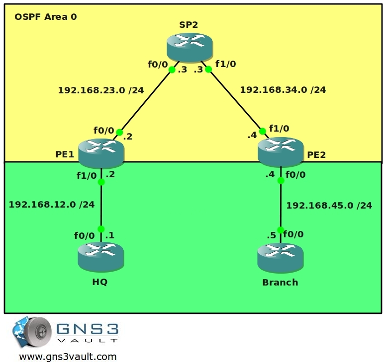
You have been dreaming of starting your own ISP for years and now the moment is finally here. You bought a couple of brand new routers and you are about to implement your MPLS backbone. Your first customer has just signed a contract for connecting two sites so there is nothing stopping you. One of your routers will be the “P” router for the backbone. The other two routers will be used as “PE” router to connect the customer’s end devices. Your customer is running RIP as their (IGP) internal routing protocol. Your backbone will use OSPF as the IGP….time to create your business!
Goal:
- All IP addresses have been preconfigured for you.
- Every router has a loopback0 interfaced configured as following:
HQ: 1.1.1.1 /25
PE1: 2.2.2.2 /25
P2: 3.3.3.3 /25
PE2: 4.4.4.4 /25
BRANCH: 5.5.5.5 /25 - Configure OSPF Area 0 at the provider side (Router PE1, PE2 and P).
- Advertise the loopback interfaces as well in OSPF.
- Ensure you have full reachability in the OSPF domain.
- Configure MPLS on all physical interfaces in the service provider domain, do not configure MPLS on physical interfaces pointing towards the customer.
- Configure VRF “customer” on PE1 and PE2 as following:
RD 100:1
Route-target both 1:100 - On router PE1 and PE2 add the interfaces pointing towards the customer to the VRF you just created.
- Ensure you can ping from within the VRF, try this as following on PE1:
ping vrf customer 192.168.12.1 - Configure RIP on router HQ and Branch. Advertise the loopbacks as well.
- Make sure you use RIP version 2.
- Disable RIP auto-summary.
- Configure RIP on router PE1 and PE2 for the correct VRF “customer”.
- Ensure you receive prefixes from the customer routers on your PE routers.
- Configure BGP AS 1 between Router PE1 and PE2.
- Configure the correct BGP address families and make sure communities are sent between neighbors.
- Redistribute RIP into BGP, use the correct address-family for the VRF “customer”.
- Make sure you keep the original metric for the prefixes.
- Ensure you have full connectivity between router HQ and Branch. You should see each other’s RIP routes that have been carried over the service provider’s MPLS backbone.
IOS:
c3640-jk9s-mz.124-16.bin
Topology:
Video Solution:
Configuration Files
You need to register to download the GNS3 topology file. (Registration is free!)Once you are logged in you will find the configuration files right here.
The How to Master series helps you to understand complex topics like spanning-tree, VLANs, trunks, OSPF, EIGRP, BGP and more.
Written by René Molenaar - CCIE #41726

good one for basic mpls config..keep it up 8)
You can run the qemu host but can’t set a default gateway?
I think it’s a normal linux host so you can set a default route on it using this command:
route add 0.0.0.0/0 gw [insert gateway ip].
If you want a host this is what I always do:
1. Use a cisco router
2. Type in “no ip routing” to disable the routing capabilities. This will turn it into a dumb host.
3. Type in ‘ip default-gateway’ to configure a gateway on it.
Voila…you have a dumb host with a default gateway to test ;D
If you don’t want to mess with Qemu but still want a host, try vmware workstation or virtualbox and run a Windows virtual machine in it. Use the “Cloud” icon in GNS3 to connect them to your routers.
hi… pleaaaaaaaaaaaaaaze i need a help
how can i give a PC ip addrees ?? then connect it to HQ ?? in GNS3
thank you alot rene;)
i meant QEMU pc and to connect it to HQ (in GNS3) i download QEMO image and binary image but i can’t give gateway>:(
You can use the “cloud” icon in GNS3 to connect a physical network card to your router. You are better of using a router to “simulate” a pc to ping etc.
on backbone i run ISIS and establish BGP connection
on CUSTOMER site i run static route.
all the route is show but i can not ping from Branch to HQ.
[color=blue]Branch#
1.0.0.0/32 is subnetted, 1 subnets
S 1.1.1.1 [1/0] via 192.168.15.4
C 192.168.15.0/24 is directly connected, FastEthernet0/0
5.0.0.0/24 is subnetted, 1 subnets
C 5.5.5.0 is directly connected, Loopback0
PE2#show ip route vrf siteA
1.0.0.0/32 is subnetted, 1 subnets
B 1.1.1.1 [200/0] via 2.2.2.2, 00:35:20
C 192.168.15.0/24 is directly connected, FastEthernet0/0
5.0.0.0/32 is subnetted, 1 subnets
S 5.5.5.5 [1/0] via 192.168.15.5
PE2#show ip route
2.0.0.0/32 is subnetted, 1 subnets
i L1 2.2.2.2 [115/30] via 192.168.34.3, FastEthernet0/1
4.0.0.0/32 is subnetted, 1 subnets
C 4.4.4.4 is directly connected, Loopback0
i L1 192.168.23.0/24 [115/20] via 192.168.34.3, FastEthernet0/1
C 192.168.34.0/24 is directly connected, FastEthernet0/1
Branch#traceroute 1.1.1.1
Type escape sequence to abort.
Tracing the route to 1.1.1.1
1 192.168.15.4 108 msec 188 msec 164 msec
2 * * *
3 * * *
[/color]
what is the problem?
a video solution is appreciate
Once again..Great stuff from Rene.
Please help – I modified the lab in such a way to accomplish the following.
1.- I connect a router(Internet-router) to HQ
2.- I run BGP between the HQ and the Internet-router
3.- I configure Internet-router to advertise a default gateway.
4.- On HQ, I redistribute BGP into RIP to advertise the default-route to Branch
Problem:
I do not see the default route on Branch – How can I resolve this?
or How can I configure the network to access the internet through the MPLS network through HQ.
Please note:
If I advertise loopbacks networks from the Internet-router, I can see them ping them on Branch.
The issue is that i do not see the default route on Branch.
Hi Rene,
the both configuration files you implement for the lab are the same.
The final configuration is the same as the startup.
Regards
Andre
Hi Andre,
I just fixed it, it’s there now.
Rene
One Word “EXCELLENT”
you rock rene!!
this is awesome!!
This lab was fun! BGP-free core. The strain on the P router is minimal. just MPLS tag switching all of it.