Scenario:
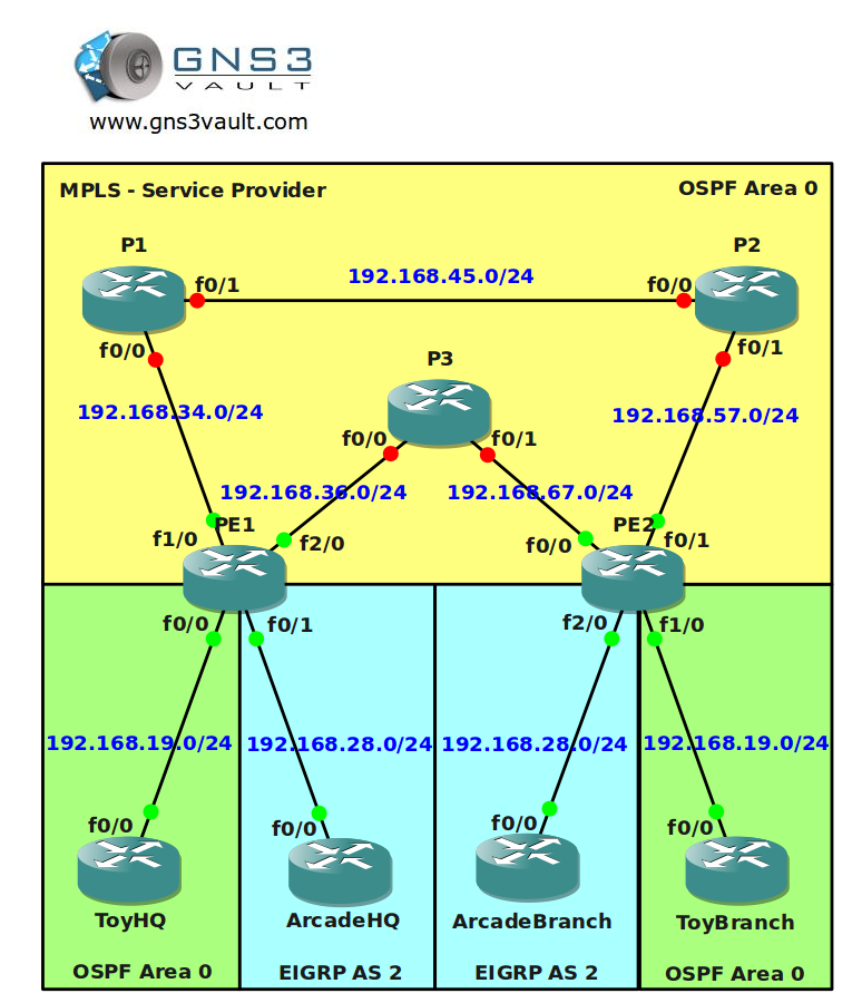
You are the senior network engineer for a large MPLS provider based in the United Kingdom. 2 of your customers called “Toy” and “Arcade” would like to use your MPLS services to connect their HQ and branch offices. Your MPLS backbone has multiple routers and one of the problems you encounter is that there is no load-sharing within the MPLS cloud. Your customers are connecting the sites using pseudowires and this is something you don’t want to change. Make sure your customers can use pseudowires and that you can use load balancing within your MPLS backbone. See if you can tag this one…
Goal:
All IP addresses have been preconfigured for you.
- Every router has a loopback0 interfaced configured.
- Configure OSPF Area 0 at the provider side (Router PE1,PE2,P1,P2 and P3).
- Advertise the loopback interfaces as well in OSPF.
- Make sure you advertise the loopback0 interfaces as /24 instead of the default /32 or you will run into trouble.
- Ensure you have full reachability in the OSPF domain.
- Configure MPLS on all physical interfaces in the service provider domain, do not configure MPLS on physical interfaces pointing towards the customer.
- Configure BGP AS 1 between Router PE1 and PE2.
- Configure the correct BGP address families and make sure communities are sent between neighbors.
- Configure a pseudowire on PE1 and PE2 to connect ToyHQ and ToyBranch.
- Configure a pseudowire on PE1 and PE2 to connect ArcadeHQ and ArcadeBranch.
- Configure OSPF Area 0 on router ToyHQ and ToyBranch. Advertise the loopbacks as well.
- Configure EIGRP AS 2 on router ArcadeHQ and ArcadeBranch. Advertise the loopbacks as well.
- Make sure you have an OSPF adjacency between the 2 Toy routers.
- Make sure you have an EIGRP adjacency between the 2 EIGRP routers.
- Ensure you have full connectivity for the customer networks. ToyHQ and ToyBranch should exchange OSPF prefixes and ArcadeHQ and ArcadeBranch should exchange EIGRP prefixes.
- At this moment you should have a working MPLS network but all traffic is being sent through P3. We are going to use MPLS traffic engineering to use P1 and P2 as well.
- Configure a tunnel10 interface on router PE1 and PE2 for VRF Toy. Make sure the tunnel is in MPLS traffic engineer mode.
- Configure the hold and setup priority to 1 for the tunnel 10 interface, set the bandwidth to 2000.
- Configure a tunnel11 interface on router PE1 and PE2 for VRF Arcade. Make sure the tunnel is in MPLS traffic engineer mode.
- Configure the hold and setup priority to 1 for the tunnel 11 interface, set the bandwidth to 2000.
- Configure the RSVP bandwidth to 2000 for all links interconnecting the P and PE routers.
- Configure MPLS traffic engineering tunnel support for all links interconnecting the P and PE routers.
- Finish your configuration so traffic for customer Toy is sent from PE1 through P1 and P2.
- Finish your configuration so traffic for customer Arcade is sent from PE1 through P3 and P2.
IOS:
c3725-adventerprisek9_ivs-mz.124-15.T13
Topology:
Configuration Files
You need to register to download the GNS3 topology file. (Registration is free!)Once you are logged in you will find the configuration files right here.
The How to Master series helps you to understand complex topics like spanning-tree, VLANs, trunks, OSPF, EIGRP, BGP and more.
Written by René Molenaar - CCIE #41726

Hi man kindly make video on on this lab since i am so interested on MPLS
waiting as soon as possible
i hope this video will bee soon, i realy need this ))
excelent videos, by the way 😉
I Wan file Final Configs of MPLS Traffic Engineering per L2TPV3 and MPLS Traffic Engineering per VRF, i realy need this, waiting as soon as possible
Thank
I will record the video but it’ll take some time, I got a big list of other videos that I have to fix before I’m doing this one 🙂
Hello Rene
I wish this video will bee soon .. I give this website to every body i know in Chicago
Most of them got your book and watching your lab
Thanks
Layth
Meanwhile take a look at this link:
https://learningnetwork.cisco.com/docs/DOC-9776
I think this should help you to configure this lab.
Hi guys
On step: Ensure you have full reachability in the OSPF domain
I am having trouble achieving full connectivity to the network 192.168.19.0/24 as its been advertised from ToyHQ and ToyBrach. Well I could subnet them further and it would work but as it stands I cant connect Toy HQ and ToyBrach to rest of OSPF network.
Any suggestions.
PE1
======================================
pseudowire-class ToyHQ-ToyBranch
encapsulation l2tpv3
ip local interface Loopback0
!
pseudowire-class ArcadeHQ-ArcadeBranch
encapsulation l2tpv3
ip local interface Loopback0
======================================
interface FastEthernet0/0
no ip address
speed 100
full-duplex
no cdp enable
xconnect 7.7.7.7 100 pw-class ToyHQ-ToyBranch
!
interface FastEthernet0/1
no ip address
speed 100
full-duplex
no cdp enable
xconnect 7.7.7.7 200 pw-class ArcadeHQ-ArcadeBranch
======================================
======================================
PE2
======================================
pseudowire-class ToyHQ-ToyBranch
encapsulation l2tpv3
ip local interface Loopback0
!
pseudowire-class ArcadeHQ-ArcadeBranch
encapsulation l2tpv3
ip local interface Loopback0
======================================
interface FastEthernet1/0
no ip address
speed 100
full-duplex
no cdp enable
xconnect 2.2.2.2 100 pw-class ToyHQ-ToyBranch
!
interface FastEthernet2/0
no ip address
speed 100
full-duplex
no cdp enable
xconnect 2.2.2.2 200 pw-class ArcadeHQ-ArcadeBranch
Hey all!
I cannot get the pseudowire to work! Any hints will be appreciated. I have read the learningnetwork doc, but what I cannot understand (and doesn’t seem to work) is a tunnel interface with no source interface…
Got it working!
can you please share the whole config files
Rene,
I have a question. Since we are deploying pseudowires, there is no need to configure VRFs. Correct? So when you say "configure the correct address families" under BGP, you are referring to vpnv4 address family?
Also, what is the best practice on the PEs? Configure different loopbacks to assign to the different pseudowire-classes or use only one loopback, since the pseudowires are differentiated by the VC?
Thanks in advance,
Katerina
Hi ,Can i see the video ….
Plz share/mail updated link on atulbhardwaz@gmail.com
On the bullet where you said "Make sure you have an OSPF adjacency between the 2 Toy routers", you must have meant EIGRP.
Dear Rene ,
Kindly upload video for this lab ,,,
and thanks man for your wonderful labs and videos..
really grateful to you
kind regards
Hi Rene
Can you make this topology video ASAP
Thanks
Hi Rene,
Thanks for all labs you make for us.
About this one, why do we have to configure bgp between PE1 and PE2?
Hi Rene, any chance for the "final configs" on this lab? Video?
Thanks for all that you do!!
Hi Rene,
can u plz hepl usby uploading this video regarding Traffic Engineering ,, need it …
Hi Rene could you please upload video solution for this one at the earliest please…..
hey guys .. i use NM-16ESW on PE1 and PE2 .. i can configure xconnect on fa1/0 on that’s router .. but why i can’t configure on fa2/0 .. ??
can anyone help me ..
What IOS version?
sorry for the late reply .. i use IOS c3725-adventerprisek9_ivs-mz.124-15.t13 .. same like Rene told on this lab ..
now i run with c7200-adventerprisek9-mz[1].124-20.T .. and i complete 15 first Task .. still working with next task
I have managed to load balance Toy traffic over P1 and P2 and Arcade traffic over P3, but I am not sure what BGP is for?
PE1#sh running-config
hostname PE1
!
ip cef
ip vrf Arcade
rd 100:2
route-target export 2:2
route-target import 2:2
!
ip vrf Toy
rd 100:1
route-target export 1:1
route-target import 1:1
mpls traffic-eng tunnels
multilink bundle-name authenticated
pseudowire-class ToyHQ-ToyBranch
encapsulation mpls
preferred-path interface Tunnel10
!
pseudowire-class ArcadeHQ-ArcadeBranch
encapsulation mpls
preferred-path interface Tunnel11
interface Loopback0
ip address 2.2.2.2 255.255.255.255
ip ospf network point-to-point
!
interface Tunnel10
no ip address
tunnel destination 7.7.7.7
tunnel mode mpls traffic-eng
tunnel mpls traffic-eng autoroute announce
tunnel mpls traffic-eng priority 1 1
tunnel mpls traffic-eng path-option 1 explicit name Top
no routing dynamic
!
interface Tunnel11
no ip address
tunnel destination 7.7.7.7
tunnel mode mpls traffic-eng
tunnel mpls traffic-eng autoroute announce
tunnel mpls traffic-eng priority 1 1
tunnel mpls traffic-eng path-option 1 explicit name Bottom
no routing dynamic
!
interface FastEthernet0/0
no ip address
speed 100
full-duplex
no cdp enable
xconnect 7.7.7.7 100 pw-class ToyHQ-ToyBranch
!
interface FastEthernet0/1
no ip address
speed 100
full-duplex
no cdp enable
xconnect 7.7.7.7 200 pw-class ArcadeHQ-ArcadeBranch
!
interface FastEthernet1/0
ip address 192.168.34.3 255.255.255.0
speed 100
full-duplex
mpls ip
mpls traffic-eng tunnels
ip rsvp bandwidth 2000
!
interface FastEthernet2/0
ip address 192.168.36.3 255.255.255.0
speed 100
full-duplex
mpls ip
mpls traffic-eng tunnels
ip rsvp bandwidth 2000
!
router ospf 1
mpls traffic-eng router-id Loopback0
mpls traffic-eng area 0
log-adjacency-changes
network 2.2.2.2 0.0.0.0 area 0
network 192.168.34.0 0.0.0.255 area 0
network 192.168.36.0 0.0.0.255 area 0
!
router bgp 1
no synchronization
bgp router-id 2.2.2.2
bgp log-neighbor-changes
neighbor 7.7.7.7 remote-as 1
neighbor 7.7.7.7 update-source Loopback0
no auto-summary
!
address-family vpnv4
neighbor 7.7.7.7 activate
neighbor 7.7.7.7 send-community both
exit-address-family
!
address-family ipv4 vrf Toy
no synchronization
exit-address-family
!
address-family ipv4 vrf Arcade
no synchronization
exit-address-family
!
ip forward-protocol nd
!
no ip http server
no ip http secure-server
!
ip explicit-path identifier 1 enable
next-address 192.168.34.4
next-address 192.168.36.6
!
ip explicit-path name Top enable
next-address 192.168.34.4
next-address 192.168.45.5
next-address 192.168.57.7
!
ip explicit-path name Bottom enable
next-address 192.168.36.6
next-address 192.168.67.7
=======================================================================
=======================================================================
PE2#sh running-config
hostname PE2
ip cef
ip vrf Arcade
rd 100:2
route-target export 2:2
route-target import 2:2
!
ip vrf Toy
rd 100:1
route-target export 1:1
route-target import 1:1
no ip domain lookup
!
mpls traffic-eng tunnels
multilink bundle-name authenticated
pseudowire-class ToyHQ-ToyBranch
encapsulation mpls
preferred-path interface Tunnel10
!
pseudowire-class ArcadeHQ-ArcadeBranch
encapsulation mpls
preferred-path interface Tunnel11
interface Loopback0
ip address 7.7.7.7 255.255.255.255
ip ospf network point-to-point
!
interface Tunnel10
ip unnumbered Loopback0
tunnel destination 2.2.2.2
tunnel mode mpls traffic-eng
tunnel mpls traffic-eng autoroute announce
tunnel mpls traffic-eng priority 1 1
tunnel mpls traffic-eng path-option 1 explicit name Top
no routing dynamic
!
interface Tunnel11
ip unnumbered Loopback0
tunnel destination 2.2.2.2
tunnel mode mpls traffic-eng
tunnel mpls traffic-eng autoroute announce
tunnel mpls traffic-eng priority 1 1
tunnel mpls traffic-eng path-option 1 explicit name Bottom
no routing dynamic
!
interface FastEthernet0/0
ip address 192.168.67.7 255.255.255.0
speed 100
full-duplex
mpls ip
mpls traffic-eng tunnels
ip rsvp bandwidth 2000
!
interface FastEthernet0/1
ip address 192.168.57.7 255.255.255.0
speed 100
full-duplex
mpls ip
mpls traffic-eng tunnels
ip rsvp bandwidth 2000
!
interface FastEthernet1/0
no ip address
speed 100
full-duplex
no cdp enable
xconnect 2.2.2.2 100 pw-class ToyHQ-ToyBranch
!
interface FastEthernet2/0
no ip address
speed 100
full-duplex
no cdp enable
xconnect 2.2.2.2 200 pw-class ArcadeHQ-ArcadeBranch
!
router ospf 1
mpls traffic-eng router-id Loopback0
mpls traffic-eng area 0
log-adjacency-changes
network 7.7.7.7 0.0.0.0 area 0
network 192.168.57.0 0.0.0.255 area 0
network 192.168.67.0 0.0.0.255 area 0
!
router bgp 1
no synchronization
bgp router-id 7.7.7.7
bgp log-neighbor-changes
neighbor 2.2.2.2 remote-as 1
neighbor 2.2.2.2 update-source Loopback0
no auto-summary
!
address-family vpnv4
neighbor 2.2.2.2 activate
neighbor 2.2.2.2 send-community both
exit-address-family
!
address-family ipv4 vrf Toy
no synchronization
exit-address-family
!
address-family ipv4 vrf Arcade
no synchronization
exit-address-family
ip explicit-path name Top enable
next-address 192.168.57.5
next-address 192.168.45.4
next-address 192.168.34.3
!
ip explicit-path name Bottom enable
next-address 192.168.67.6
next-address 192.168.36.3
boss please video
Hey Rene,
Can you please add a video of this topology?
Thanks in advance
video????????????????????????????????????????????
Hi Renee,
I hope you have a video for this lab. Thanks in advance.
L3nnArd
Can you upload the final config for this topology?
Hi Renee,
Please upload video and config file for this lab. Please ..
Anyone here please share config file for this lab.. please